
We’ve spent several months now designing and testing the sensor devices before settling on the final design. It’s not something our participating groups or engineers need to know about, but there are some people who want to know how they work, and why they are the way they are. There are two types – standalone units that save temperature and relative humidity data on the device itself, and internet-connected ones that send the data to the internet via a mains-powered hub that connects to the Wi-Fi. They are the same apart from the addition of a 433 MHz radio transmitter.
In the design, we wanted the devices to be cheap but feasible for a hobbyist to construct. In addition, the standalone sensor unit had to run from batteries and provide straightforward access to the readings.
We settled on an ESP8266-12F or ESP12F because, although not the most power thrifty microprocessor, it has WiFi and a large flash memory, plus the well supported Arduino IDE for loading code, and is cheap !
Power consumption is kept reasonable by a deep sleep function, waking briefly to read the temperature and humidity.
Additionally for a short period after power-up, it broadcasts an Access Point, giving a chance to connect a mobile phone or similar and download the stored data for subsequent analysis.
It requires a supply voltage of 3.3v ideally but is fine down to 3v. Alkaline batteries start at above 1.5v so 2 x AA will power it for a few days but soon the voltage drops below 1.5v. Lithium batteries have a much steadier discharge voltage graph, and continue to provide 1.5v until near the end of life, so we have chosen to use these. (Not to be confused with rechargeable Lithium Ion batteries.) Calculations indicate a year of life, but we haven’t had time to test this for real.
The sensor unit we use is a DHT22 which also keeps working down to 3v.
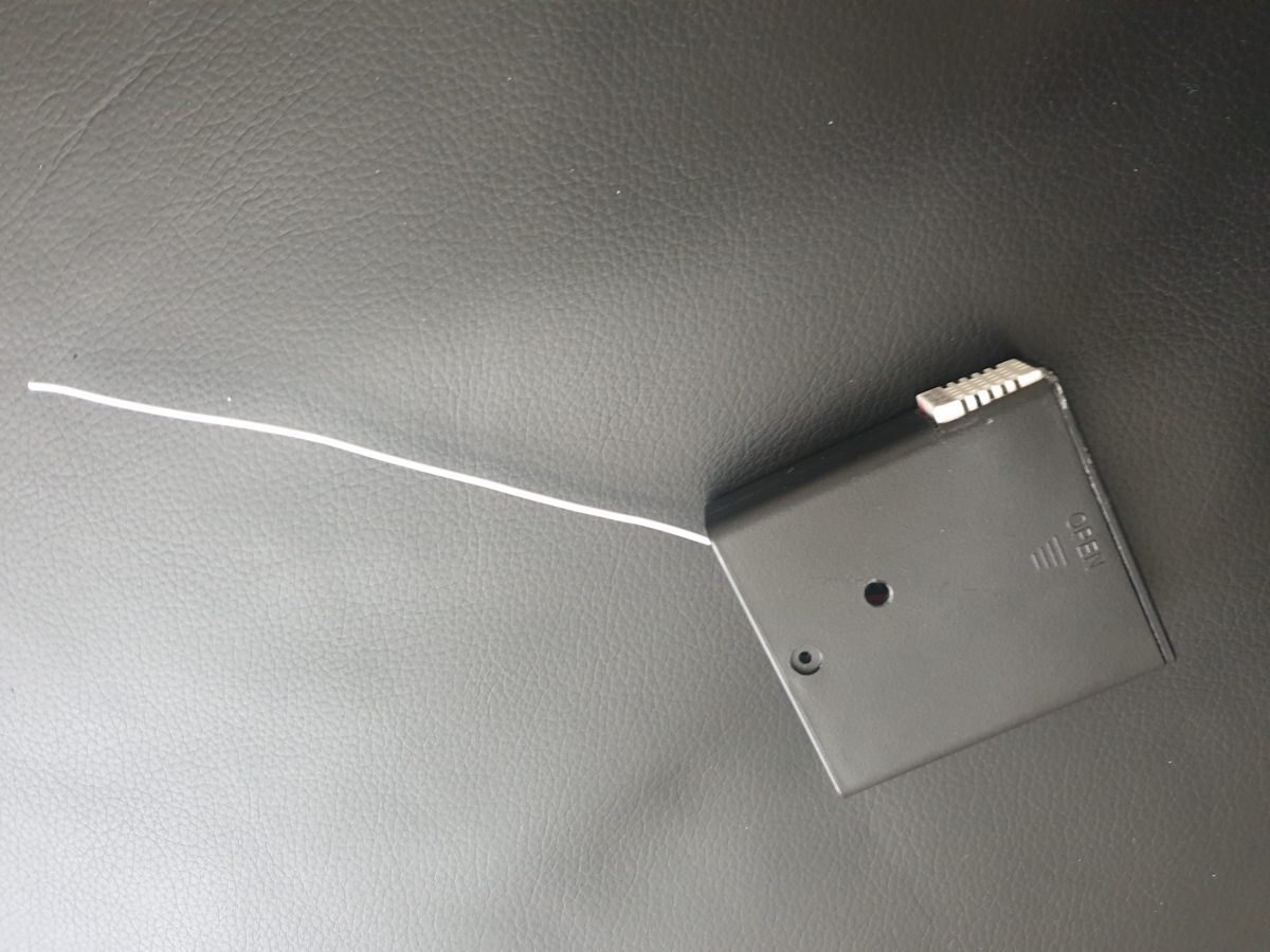
The entire unit thus has an ESP12F, DHT22 and battery box, and involves only a few soldering joints.
Flashing code to the ESP12F is not as easy as it is for the variants which include a micro USB socket, but these come with added power consumption.
There are various methods of flashing code: easiest is to use a “burner board” which costs a few £s. There are cheaper methods which involve a little more expertise.
Once soldered together it’s no longer possible to fit the ESP12F into the burner board, so the code we use includes an Over The Air or OTA function that means if we really have to, we can amend the code, but this does not work remotely so we hope it will not be necessary.
There is no real time clock in the ESP12F and adding one would have increased complexity and expense. Instead we calculate the time using the sensor reading interval, typically 5 minutes.
However the internal timekeeping in an ESP12F is mediocre, leading to a drift in the software clock used to schedule readings. Usually we are taking a reading every 5 minutes and it’s not time critical, but after a week the real time and calculated time could be an hour or so different. We obtain the starting time from the mobile phone used to connect to the Access Point (it’s available from the Web page the phone hosts). Since it’s necessary to connect again to download the data we can get the end time and thus the possibility of scaling the readings to provide more accurate times.
Once a sensor has finished with the Access Point the WiFI signal is turned off so there is no transmitted signal revealing a device somewhere that might be worth hacking or interfering with.
Coming soon: parts and construction details for the standalone sensor.